The following workflow describes a method for producing 3D image-overlain digital elevation models from photographic imagery using Agisoft PhotoScan Professional (academic license $550 USD from www.agisoft.ru). Specifically written for delta experiments, but can be applied elsewhere.
Image collection:
With flow off and water level lowered:
· Ensure that there are immobile ground control points for scale and for reference between successive models
· Using a digital camera (any digital camera will work, images must be corrected for lens distortion, however, either in-camera or with separate image processing tools – Agisoft can do this), take images from above at multiple angles and from multiple locations, ensuring that all surfaces of the delta are covered by at least 2-4 overlapping images (i.e. any parts where there may be shadowing from some angles)
o Ensure that shadows, light reflections off water surface, etc. are minimized, as they can move with different camera angles and make image correlation difficult/less accurate)
o The number of photographs and the fields of view depend on the resolution of interest. Increasing numbers of images significantly increases processing time.
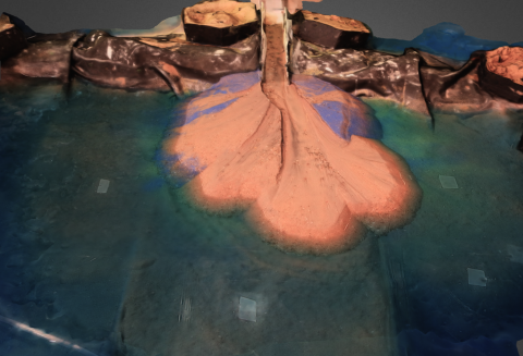
o It’s important to have a surface with distinctive enough points so that the software can make decent correlations (i.e. a clean flat, white surface isn’t ideal)
Image Processing
· Check and delete any blurry images as they will complicate correlations.
· Import photos from delta experiments into Agisoft (found at www.agisoft.ru, ca. $550 USD)
o Select “add photos”
o Photos can be processed in “chunks”, which build individual models for each chunk (you can click “add chunk” to create new ones.
· Under the “workflow” tab, select “batch process”
· Click “Add”
· Select job type from drop down menu. Start with “align photos” using settings as needed (more accuracy results in slower processing, less precision). Hit OK.
o This step automatically aligns images based on pairing of features (e.g. sand grains of different colors, etc.) and creates a “sparse cloud” of elevations based on those points
· Continue by adding the remaining job types as follows:
o “optimize alignment” - optional
o “build dense cloud”
§ This step uses the previously completed alignment to develop a dense point cloud. This step can take many hours, depending on the desired quality, the number of images, etc.
o “build mesh”
§ This creates a surface which allows draping of the imagery over the model
o “build texture”
§ Overlays the imagery onto the model mesh
· Once you have added jobs, select ok and it will start the batch processing. This could take a few tens of minutes to many tens of hours, depending on your parameters and the number/resolution of your images (and it will use ALL of your processing power – so it’s a good time to go get a beer)
· If you are working with a large quantity of photographs or want very high resolution models, the software allows you to process chunks separately on separate computers. You can then merge chunks later.
· At any point, you can crop or delete portions of your model to speed up processing. This is done in the toolbar with the “rectangle” “circle” or “freeform” selection icons and the “delete selection” and “crop selection” icons
DEM referencing/scaling:
· Select the “Ground Control” tab
· Right-click on your ground control points in the DEM/imagery and select “Create Marker” – this places a marker on that location in the DEM
· You can then add the local coordinate positions and errors in positions for each ground control point under the “Markers” box
· If no local coordinate system was established, images can still be scaled using reference markers. After placing markers with known distances from each other into the model as above, select the markers you wish to provide a scale for (at least 2) using CONTROL-Select. Right click the selection and select “create scale bar”
· Under the “scale bars” box, input the distance and error (if known).
· Once your control points have been entered, hit the update button (round blue arrows) to apply the scaling/positioning to the point cloud
For purposes requiring detailed recording of data processing methods, the console tab allows you to save the log of console operations during the session by clicking the “save log” icon. Unless you save the log, these details will be lost at the end of each session.
Downloadable example models from the 2014 SEN Utrecht Workshop collaborative experiment can be found at the following URLs: