1.1 Pipeline Setup
Now that the head tank is operational a piping network can be connected to the tank via flange gaskets. The piping network should be designed to deliver water to whatever experiments you plan to run in your laboratory while considering the drawdown of water from the head tank.
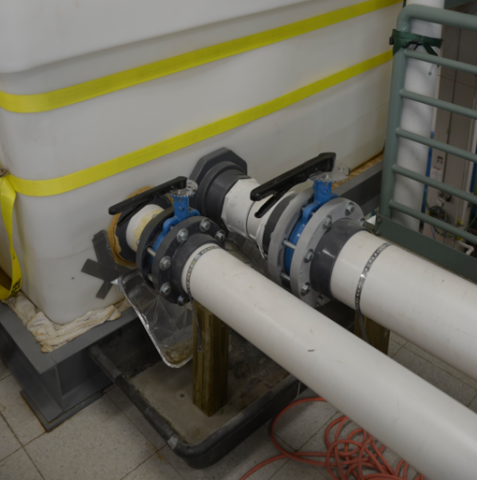
We have two pipelines, a six-inch and a eight-inch pipe, that connect the head tank to the experimental facilities. Each pipe is equipped with elbows, bends and flanges to reach the different flumes, if and when needed. On the outside of the tank about two feet down from the pipes connections are butterfly valves. Theses valves are only to open and close the pipes when they are in and out of use to prevent draining the tank fully or the entry of air into the pipes.

Figure 1. Depiction of the butterfly valves connected to the head tank for the 6" and 8" pipes.
Further down these pipes, it will be necessary to install a flow meter. Depending on the lab configuration and your budget and the range of flow rates that you will be using, you will have to design your flow measurement system. In order for the flow meter to work adequately it must be far away from irregularities in the pipe, fittings or valves. This distance should be given by the flow meter's manufacturer.
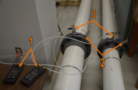
In our case we installed an orifice plate on each line. The orifice plates are connected to digital manometers, we used a Dwyer Series 490, and the system was calibrated as illustrated in the next section. Digital manometers take up little space and their installation is simple. However a digital manometer can and will eventually break and can be expensive to replace.

Figure 2. In numerical order, 1 is the digital manometer, 2 is the orifice plate protruding from its housing and 3 is the valves connecting the assembly.
It is important to notice here that we chose to install orifice plates to measure the flow rate because they are easy to maintain and they are not at risk to be damaged by fine material (silt and clays) that may be in the water. A downside to using an orifice plate in the six and eight inch pipes is the limited range that an orifice plate can operate at. For a particular size orifice plate you will only be able to use it for a certain flowrate range. An alternative is to fabricate a set of pipes that are in parallel with each other connected to the six or eight inch pipe, or whatever size pipe you are using to supply your experiment. Each of the parallel pipes should have a valve on their inlet side. In each of the pipes a different orifice plate will be used for their different flowrate ranges, which may lead to various sized pipes to fit the orifice plates. From there each pipe will have a manometer connected to it, preferably done with a standard U-tube manometer. Although this system is labor intensive to make it is advantageous due to its reliability, affordability, durability, and usefulness for a broad spectrum of flows.
1.2 Valve Pro's and Con's
Gate valves are inexpensive, available in multiple sizes, and are bidirectional. Although they are mainly used as on/off valves specific types can be used to modulate flows. Another advantage is their reasonable performance with slurries. However these valve open and close very slow and have low pressure limitations.
Butterfly valves can be used diversely. They can be used to allow variable flows or as simple on/off valves. These valves are compact in design, have a high coefficient of flow and come in whatever pipe sizes you may need. A con of this valve is the difficulty of opening and closing under pressure.
1.3 Volumetric Calibration of a Head Tank
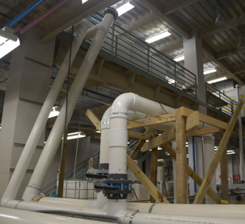
In order to get an accurate calibration of each of your pipes, going from the head tank to your experiments, a calibration tank/basin will need to be large to hold the volume of water produced by each pipe individually at their maximum flowrate for a duration of at least five minutes. The longer the duration time the more accurate the calibration up to a reasonable point. The pipes leading to your experiment will need to at some point lead to the calibration tank as well, preferably close to the experiment. Figures 3 and 4 show how we have connected same diameter pipes to the six and eight inch pipes that proceed to the calibration tank. Valves are installed to the pipes to variate the flow for volumetric calibration.

Figure 3. Depiction of the 6" and 8" pipes connection to the calibration tank.

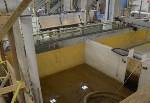
Figure 4. Depiction of the calibration tank and the 6" and 8" pipes draining to it.
Calibrating the six and eight inch pipes from the head tank will require two individuals. One person will man the manometer and a stopwatch while the other will operate the valve leading to the calibration tank. Given the dimension of the calibration tank designed and the visible water depth you can infer the volume of water in the tank. A simple way of measuring the volume in the tank is to mark a lower and upper line into the side of the tank at reasonable depths. Knowing the difference or depth between the upper and lower lines, and the tank's outer dimensions a set volume of X can then be calculated. Once the water level reaches the lower line, after the valve has been opened to whichever position and the tank is filling up, the stopwatch is then started. When the water level reaches the upper mark the stopwatch will be stopped and the elapsed time will be recorded. While the calibration tank is filling up the manometer reading should be written down. Flowrates can be generated from the set volume and recorded times that elapsed. This process will be repeated for different valve positions, or reasonable increments throughout the valve's operating range, until you have enough data to create an accurate flow curve, flowrate vs. pressure difference, for each pipe.