1.1 Design Requirements and Logistics
The design of your head tank depends largely on your demands, space limitations and budget:
- What range of flow rates do you need for your experiments?
- Is there a water storage basin in your lab?
- Are you restricted by space?
- Do you have an elevated place that is structurally capable of supporting a tank when operating (full)?
These questions are necessary to think about not only for your current experiments but also future ones.
1.2 Head Tank Ideology
Think of the example provided as hypothetical design requirements rather than a strict copy and paste design. As mentioned your requirements, space, and financial stand point may be very different so please do adapt the example for your benefit but do so with safety in mind.
The purpose of a head tank is to fix the energy level on your pipes to guarantee a steady and consistent water supply to the experimental facilities. A pump is not a accurate way to supply water to an experiment because of its fluctuation on the energy level.
The head tank's volume depends on the current and future demands from the laboratory's experiments. The tank should be sized to where it can hold enough water to supply each experiment's maximum flowrate for a duration of ten to fifteen minutes. Meaning the sum of each experiment's max flowrate for ten to fifteen minutes where the total max flowrate is multiplied by time to yield the ideal volume of the tank. Again you may be constricted by space so this design philosophy may not work for you. One option is to consider the largest flowrate required for all of your experiments and to size your head tank to hold at minimum a volume equal to the largest flowrate considered multiplied by a time duration of ten to fifteen minutes, as mention. In regards to the head tank as a structure, cast iron is an ideal material to use. Due to the purpose of creating an inexpensive head tank we used a two thousand gallon, size is dependent on your lab requirements, plastic tank with ratchet straps wrapped around it to add rigidity to its walls.
1.3 Laboratory Layout
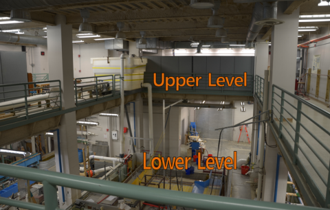
In our laboratory we have two floors with the experimental setups on the lower level excluding a small flume on the upper level. The upper level is our point of higher elevation for the placement of the head tank. In addition, we have a relatively large pre-existing water storage basin that is used as our water source. In order to move the water from the basin to the head tank a pump is required.

Figure 1. Depiction of our laboratory's current head tank and experimental setups.
If your laboratory does not have a pre-existing basin an optional design is to place a large reservoir(s) on the lower level, ground floor, of the lab and a smaller tank at a higher elevation i.e. an upper level or tall support frame. The experiments that are supplied by this system must then recirculate the water back into the large reservoir(s), as with our experiments as they recirculate the water supplied to them back into the basin.
1.4 Pump Setup
At this moment in the design it is important to consider what type of pump you wish to use. Different pump types will have different performance usages. In our lab we have to move water from the basin to the head tank, i.e. 20+ feet above the water level of the basin. We used a centrifugal pump that the contractor had in stock and sold to us at a discounted price. The pump characteristics were close enough to our needs, so we could accept this solution. However, if the budget allows it, we strongly recommend purchasing a pump that is adequate for your system.
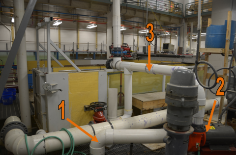
As a side note, when moving any quantity of water with a piping system it is extremely important to support/fix/brace these pipes with a heavy emphasis on safety. The pump has a suction pipe to draw water from the basin. The inlet of the suction pipe should be deep enough into the basin that if the basin’s water level does happen to fluctuate, the inlet will always be submerged.

Figure 2. In numerical order, 1 is the suction pipe, 2 is the pump and 3 is the discharge pipe.
Downstream of the pump the discharge pipe splits into two pipes. One pipe, the bypass, will discharge straight back to the basin, while the other will discharge into the head tank as shown in Figure 2.

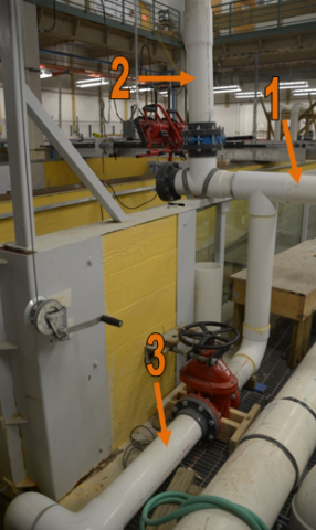
Figure 3. In numerical order, 1 is the discharge pipe directly from the pump that splits to two pipes, 2 is the discharge pipe to the head tank and 3 is the discharge pipe to the basin.
If the pump were to suddenly shutoff the column of water going up to the head tank could come back down as a transient wave and damage the pump. A perfect design to avoid this scenario would be to install a cutoff valve immediately downstream of the pump, according to manufacturer's specifications, and prior to the split to two pipes. Due to the proximity of a cutoff valve to the split, two valves, and pump it is not possible for us to implement one now, though the current design has sufficed.
1.5 Head Tank Overflow System
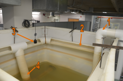
On to the head tank, the line form the pump is as low into the tank as possible with a diffusing outlet. As the pump sends water to the head tank it will fill up to whatever level desired. The level will be determined by the location of your overflow. We have four PVC pipes connected by ninety degree bends to form a rectangular arrangement. Each PVC pipe has a quarter of its circumference removed from its cross section. One of the four PVC pipes is cut in half and adjoined at the center with a tee fitting. The tee fitting connects the rectangular arrangement to the drain pipe. The drain pipe runs down to the bottom of the tank, takes a ninety degree bend and comes out of the side of the head tank, through a flange gasket, and drains down into the basin. Figure 4 gives a visual representation of the previously described arrangement. It is important that this main line has a considerable capacity, enough to handle the quantity of water being sent to it from the pump.

Figure 4. In numerical order, 1 is the discharge pipe from the pump to the head tank, 2 is the overflow weir, 3 is the float mechanism and 4 is the drain pipe.
The reason we have the inlet to the draining system going around the inside perimeter of the head tank is because it acts as a weir. The longer the weir's length the less the head tank's water level will fluctuate. The specific design of the weir is not a general rule of thumb however the concepts like weir length and pipe capacity should still hold their importance in your design. A few inches above the perimeter weir we have a float mechanism. If the water level reaches the height of the float it will lift the float relieving tension on the line it hangs which in turn cuts off the power to the pump. This is a safety mechanism in case the tank is on the verge of overflowing.